14 February 2025 by bloho — Ayush Samanta, New Delhi
Part 1: Simple explanation
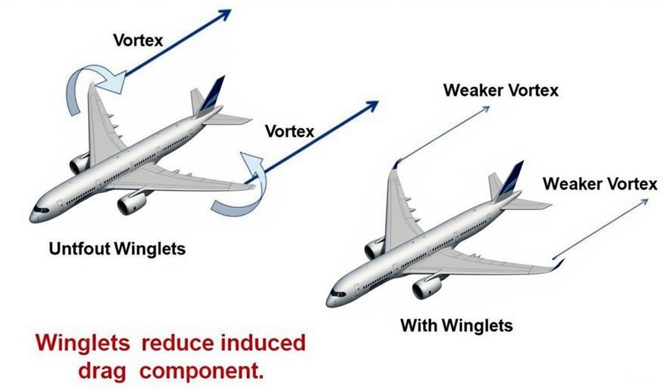
The basic idea of a “winglet” can be associated with a barrier. When a plane is in flight, it’s wings have two regions differentiated by pressure. The above part of the wing has low pressure, while the lower part of the wing has high pressure. And the tendency of the high pressure region to move up towards the low pressure region tends to create the phenomenon “wingtip vortices”.
1a.1: The directions of wingtip vortices
these wingtip vortices generate downwash behind the airplane, which tilts the local relative airflow downward. Since lift is always perpendicular to the relative airflow, the lift vector tilts backward. The backward component of this tilted lift acts as induced drag.
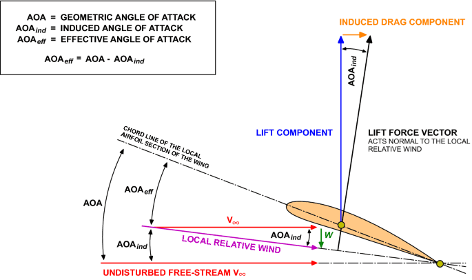
1a.2: How induced drag component affect the angle of attack
Part 2: Going a little deeper into “why?”
2.1.1 Effects of induced drag
Induced drag is the drag produced whenever an airplane demands lift. As explained above, the wing creates wingtip vortices that push air downward, tilting the lift force slightly backward, so part of lift effectively turns into drag. To then overcome this drag, the aircraft needs more thrust, burns more fuel, climbs less efficiently, and loses range and endurance.
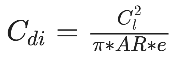
2.1.2 Drag coefficient
The induced drag coefficient C(d i) is equal to the square of the lift coefficient C(l) divided by the quantity: pi (3.14159) times the aspect ratio AR times an efficiency factor e. The value of the efficiency factor is 1.0 for an elliptical wing and some smaller number for any other planform. The value is about .7 for a rectangular wing.
Planform: the shape and layout of an airplane's wing
2.1.2 Vortex analysis (Easy to visualize simulations)
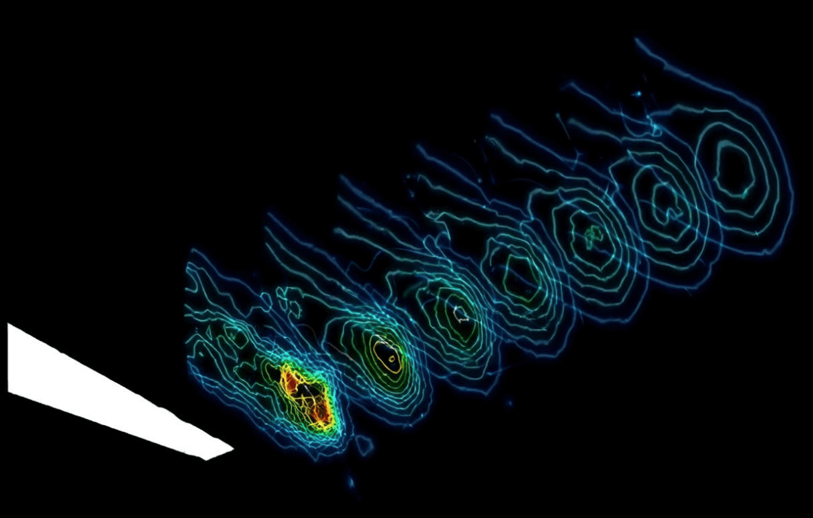
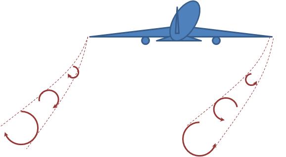
1a.3: Vortices formed for wing without winglet
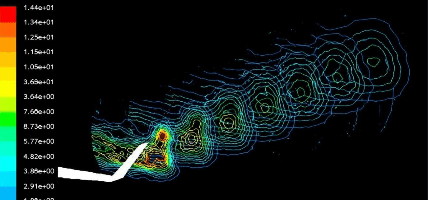
1a.4: Vortices occurring for the blended winglet at 8° angle of attack
In (1a.3) : the case without the winglet, the pressure difference between the lower and upper surfaces of the wing is allowed to equalize freely at the tip. This causes the flow to roll up immediately into a single, strong wingtip vortex right at the trailing edge. The CFD contours show a compact, high-intensity vortex core forming early, which is a clear signature of strong downwash and a significant rearward tilt of the lift vector. Aerodynamically, that translates directly into higher induced drag and poorer efficiency.
In (1a.4): The winglet acts as a physical and aerodynamic barrier that redirects the spanwise flow and stretches the vortex system vertically and downstream. Instead of one dominant vortex forming abruptly, the wake shows multiple weaker, more distributed vortical structures that develop more gradually. This means the induced downwash at the wing is reduced, the lift vector remains closer to perpendicular to the freestream, and the effective aspect ratio of the wing is increased. The net outcome is the same lift being produced with less energy lost to the wake, which is why the configuration with the winglet is objectively more efficient.